Lockdown projects
As the UK moves into another lockdown, I think back to our first one, unbelievably six months ago. Like many engineers, I grasped the opportunity to work on a few personal projects at home, and to further develop skills and knowledge. As a technical writer, I like to keep my skills current and my expertise as practically based as possible. During early April, I bought an STM32 Nucleo L476G development board as the base platform for my projects. I’ve been busy with I2C tutorials, interrupt service routines, using the LSM303AGR MEMS sensor, and the ST MEMS multi-sensor board. I’ve learnt a lot and had some fun. There was no particular reason why I picked the STM32 product family; it just seemed to be complete, with a full IDE, BSPs, and libraries. Everything I wanted was also available from stock.
Opamps next on the list
As the months went by, I was crossing off lots of practical topics from my to-do list. A few weeks ago, I advanced to the next item on the list; opamps. I’d covered them in the distant past when I did my EE exams, but I figured that I ought to revisit them. Given that the humble 741 is in production 57 years since its launch, opamps must still have a purpose.
I started reviewing datasheets and opted to buy some LM358, a device that has become a standardised part made by several manufacturers to the same specification initially developed by National Semiconductor. I’m not sure how old the LM358 is, but it must be similar to the 741 in vintage.
Powering an opamp
Ah, I thought, I’ll probably need a dual rail power supply to power the device, so I’d better find a DC/DC converter to use. I don’t need a negative rail for all projects, but it’s more fun stretching the brief! It didn’t take long to find a compact dual-rail single inductor device, the Linear Technology (now Analog Devices) LT3582. The LT3582 was launched in 2009 and is still in production. Two converters form the architecture of the LT3582, the boost for the positive output, and an inverting one for the negative rail. Device configuration uses a set of I2C registers, and even better, I found a low-cost evaluation board from MikroE.
Evaluation board eases prototyping
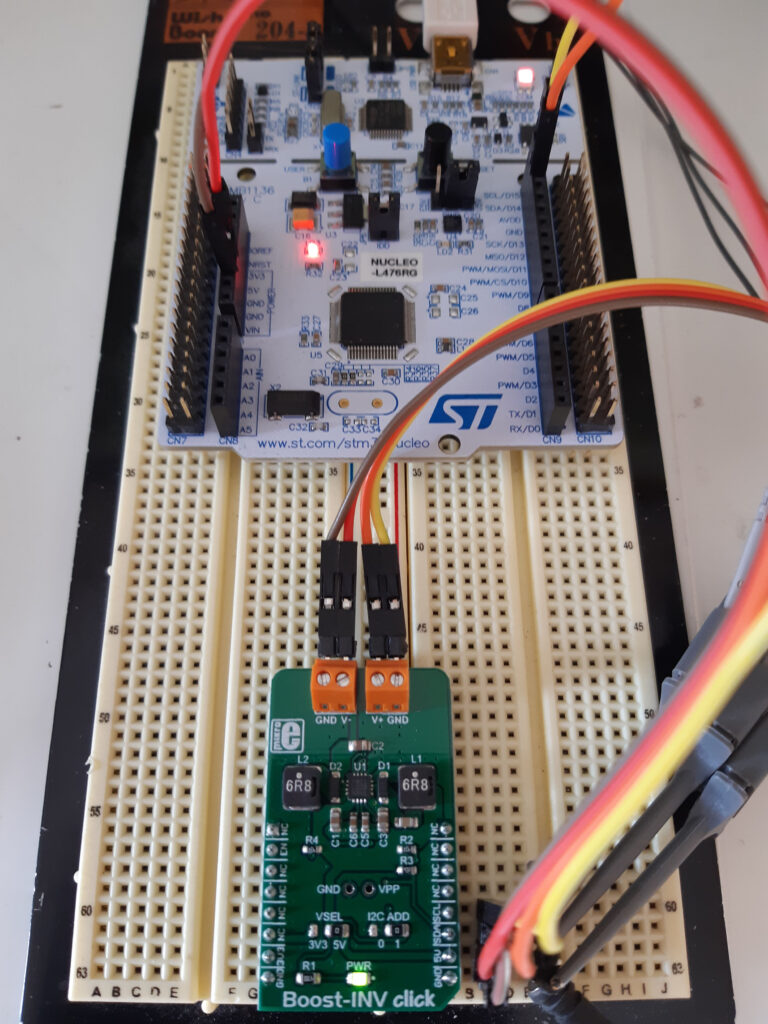
The MikroE Boost-INV uses the MikroE click board format, a convenient pin layout that caters for power and interfacing. A click board to Arduino Uno shield is available that permits connecting two click boards to an Arduino shield pinout, but I opted to use a breadboard instead.
It didn’t take long to write some code to control the LT3582 from the Nucleo-L476RG, the only minor challenge was that the Boost-INV documentation appears to give the wrong I2C addresses, but an I2C scanner program rectified this reasonably quickly.
The positive output can be programmed between +3.2 VDC (0x00) to +12.75 VDC (0xBF) in 25 mV steps, and the negative rail from -1.2 VDC (0x00) to -13.95 VDC (0xFF) in 50 mV steps.
I opted for + 10 VDC and – 10 VDC outputs for which the voltage output control registers REG0 and REG1 were set to 0xB0 and 0x88 respectively. The screen dump from my MSO highlights the process of turning the outputs off, setting the voltages, and re-enabling the output. A soft-start circuitry permits setting a ramp-up of the outputs in a controlled manner to limit peak currents.
In addition to configuring the voltage via I2C, you can also program the LT3582’s settings to be permanent by programming the on-chip non-volatile OTP memory.
Product life cycle planning
Setting up the LT3582 for my opamp projects was really interesting, but it left me wondering how the semiconductor industry deals with product life cycle planning and obsolescence.
The LT3582 is 11 years old; the 741 is 57 years old. At what point does a semi vendor decide to move a component from production to not recommended for new designs. Last time buy, and obsolescence will then follow a prescribed time afterwards. If the device is still selling in significant quantities and the fabrication process is still current, then it must be a hard decision to make. Some devices will be superseded as new iterations become available. There are many factors to consider, including whether a competitor has a similar device still in production.
No doubt statistical analysis of a device’s life cycle yields the basic concepts of product planning as well as determining the likely time frame for obsolescence. There are major differences in some product groups, memory, for example, means it is unlikely a one-size-fits-all approach will work.
What is your viewpoint? How does a product’s availability influence a new design? Please discuss on LinkedIn, and I’ll capture the salient points in my next blog.